-
-
(+91) 987 909 1953
(+91) 846 040 4010
Ribbon Blender
Ribbon Blender Machine

Ribbon Blender – Construction and Operation
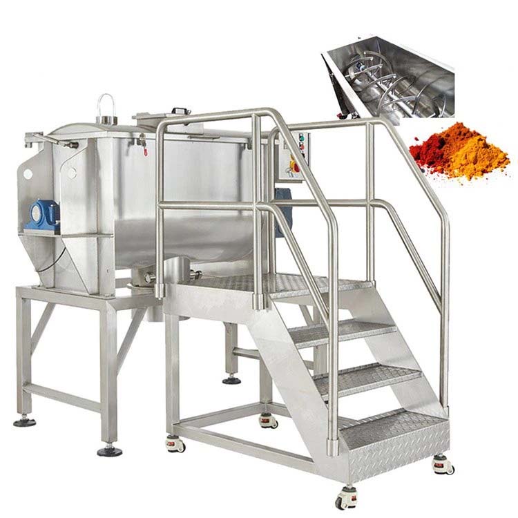
A ribbon blender consists of a U-shaped horizontal trough containing a double helical ribbon agitator that rotates within. The agitator’s shaft is positioned in the centre of the trough and has welded spokes on which the helical ribbons (also known as spirals) are welded. Since the ribbon agitator consists of a set of inner and outer helical ribbons, it is referred to as a “double" helical ribbon agitator. The gap between the ribbon’s outer edge and the internal wall of the container ranges from 3 to 6 mm depending on the application. Figure 1 shows internal and external ribbon spirals on the agitator shaft located with the blender container.
The ribbon agitator is powered by a drive system comprised of a motor, gearbox, and couplings. Ribbon blenders are generally powered by 10 HP to 15 HP motor for 1000 kg of product mass to be blended. The specific power may range from 3 to 12 kW/m3 depending on the products to be blended.
The agitator shaft exits the blender container at either end through the end plates bolted or welded to the container. The area where the shaft exits the container is provided with a sealing arrangement to ensure that material does not travel from the container to the outside and vice-versa. The blender assembly along with the drive system components viz. motor, gearbox, couplings and bearing supports is mounted on a supporting frame.
The charging of material in the blender is generally through nozzles or feed-hoppers mounted on the top cover of the blender. The inlet cover also provides maintenance and cleaning access to the inside of the blender. An external jacket can also be provided on the blender container for applications which require heating or cooling of product material
The materials to be blended are loaded into the ribbon blender, typically filling it to between 40 and 70 percent of the total volume of the container. This is generally up to the level of the outer ribbon’s tip. The ribbon agitator is designed to operate at a peripheral speed (also known as tip speed) of approximately 100 metres / minute, depending on the application and the size of the equipment. A spray pipe for adding liquids can be mounted above the ribbons. For materials that tend to form agglomerates during mixing, high speed choppers can be provided for disintegration of the agglomerates. Figure 2 shows an assembly of a 3000 litres working capacity ribbon blender.
During the blending operation, the outer ribbons of the agitator move the material from the ends to the center while the inner ribbons move the material from the center to ends. Radial movement is achieved because of the rotational motion of the ribbons. The difference in the peripheral speeds of the outer and inner ribbons results in axial movement of the material along the horizontal axis of the blender. As a result of the radial and the counter-current axial movement, homogenous blending is achieved in short time. Blending is generally achieved within 15 to 20 minutes of start-up with a 90 to 95 percent or better homogeneity. The particle size and its bulk density have the strongest influence on the mixing efficiency of the ribbon blender. Ingredients with similar particle size and bulk densities tend to mix faster as compared to ingredients with variation in these attributes.
After blending, the material is discharged from a discharge valve located at the bottom of the trough. The discharge can be fitted with any of various valves, viz. slide-gate, butterfly, flush bottom, spherical and other types depending on the application. The operation of the valves can be manual or pneumatically actuated. Ribbon blenders can be designed for multiple discharge ports. Unlike tumbling blenders where 100% discharge of material is achieved by gravity, in a ribbon blender the material is discharged by rotation of the ribbon agitator. It is practically difficult to achieve 100% discharge in the ribbon blender. Also, higher clearances between the external periphery of the outer ribbon and the container can result in unmixed spots at the trough bottom and can lead to discharge problems.
The motion of the ribbons near the vessel walls can in result in “pinch" points, or regions of high shear and compression, which may damage fragile materials and cause attrition. In some case this can also lead to friction and heat generation resulting in product degradation.
An alternate design to the ribbon agitator is the paddle agitator which can handle fragile material. The paddle agitator is composed of both forward and reverse paddles in place of the ribbon. The paddles are positioned to move the material in opposing lateral directions as well as in a radial direction.
The paddle design is generally employed where friable materials are being blended, and when batches as small as 15% of the total capacity are going to be mixed in the blender. The ribbon design is appropriate for low and medium duty applications (generally free flowing materials), while the paddle design is suitable for heavy duty applications (wet materials, heavy metal powders). In some cases a hybrid-design of paddle and ribbon agitator may be used.
Applications of Ribbon Blenders
Ribbon blenders can be designed to operate in both batch and continuous modes. Batch type blenders can be built up to capacities of 50 m3. The ribbon blender’s versatility for blending solids combined with it ability to perform heating, cooling, coating, and other processes make it a very popular blender. The following are the applications of the Ribbon Blender:
- Blending large volumes of dry solids.
- Dry powder to wet phase mixing.
- Mixing of bulk drugs, chemicals, and cosmetic powders.
- Dry Blending of capsule formulations.
- Lubrication of dry granules in large quantity.
- Heating, cooling, and drying of materials.
- Coating solid particles with small amounts of liquids to produce formulations.
Materials commonly blended in the ribbon blender are as follows:
- Abrasives
- Engineered plastic resins
- Pesticides and herbicides
- Animal feeds
- Epoxy resins
- Pet foods
- Bakery premixes
- Eye shadow
- Pharmaceuticals
- Bird seeds
- Face powders
- Pigments Cake mixes
- Fertilizers
- Plastic powders
- Carbon black
- Fire retardants
- Polyethylene
- Chemicals
- Gypsum
- PVC compounding
- Cleaning compounds
- Instant breakfast cereals
- Spice blends
- Dietary supplements
- Instant drink blends
- Talcum powders
- Dried food products
- Laundry detergents
*Specification can be changed as per customers requirements
Ribbon blender technical specification
| Model | Working capacity liters |
Total Capacity/ liters |
OUTPUT RPM |
Total HP required APPROX |
| RB - 200 | 200 ltrs | 300 ltrs | 40-65 | 2 to 3 HP |
| RB - 300 | 300 ltrs | 400 ltrs | 40-65 | 3 to 5 HP |
| RB - 500 | 500 ltrs | 750 ltrs | 30-45 | 5 to 7.5 HP |
| RB - 1000 | 1000 ltrs | 1500 ltrs | 30-40 | 7.5 to 10 HP |
| RB - 1500 | 1500 ltrs | 2000 ltrs | 30-45 | 10 to 20 HP |
| RB - 2000 | 2000 ltrs | 2500 ltrs | 30-45 | 15 to 30 HP |
| RB - 2500 | 2500 ltrs | 3000 ltrs | 30-45 | 20 to 30 HP |
| RB - 3000 | 3000 ltrs | 3500 ltrs | 25-30 | 20 to 30 HP |
| RB - 4000 | 4000 LTR | 5000 LTR | 25-30 | 20 to 30 hp |
| RB - 5000 | 5000 LTR | 6000 LTR | 25-30 | 30 TO 40 HP |
| RB - 10000 | 10000 LTR | 12500 LTR | 20-30 | 40 TO 50 HP |


